How to create a flow
To create a new flow in DaVinci, you add nodes that perform specific actions and join them together with logical operators.
Creating the flow
To begin creating a new flow, click Add Flow on the Flows tab. You’ll be presented with three options:
-
Template Flow: Create a flow starting with a template created by Ping.
-
Import Flow: Import a flow that was exported in JavaScript Object Notation (JSON) format. If you import a flow that uses a connector that you haven’t configured, you’ll need to configure it before using the flow.
-
Blank Flow: Create a flow starting from a blank canvas.
Adding nodes
Nodes represent specific actions within a flow. When you first create a flow, it has no nodes, but you can add nodes in multiple ways:
-
Click the icon in the lower left of the flow canvas. This creates a new node without any connection to an existing node.
-
Click and drag from the start or stop icons on the left or right of an existing node. This creates a new node before or after the existing node.
-
Click and drag from the dot on the left or right of an existing logical operator. This creates a new node before or after the logical operator.
-
Right-click an existing node and click Clone.
-
Select one or more existing nodes, right-click them and click Copy, then right-click the canvas and click Paste Nodes.
Using logical operators
When you click and drag a line from one node to another, a logical operator is created between the two nodes. This logical operator determines whether the subsequent node runs.
A label indicates the type of logical operator. To change the type, right-click the label or the line itself, then select another type.
Flow patterns
By connecting nodes with logical operators, you can create relationships between the nodes.
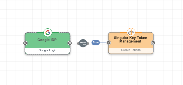
In this example flow, the user is first prompted to sign on with Google. After the user successfully authenticates, the second node creates tokens for the user and redirects them back to the relying party.
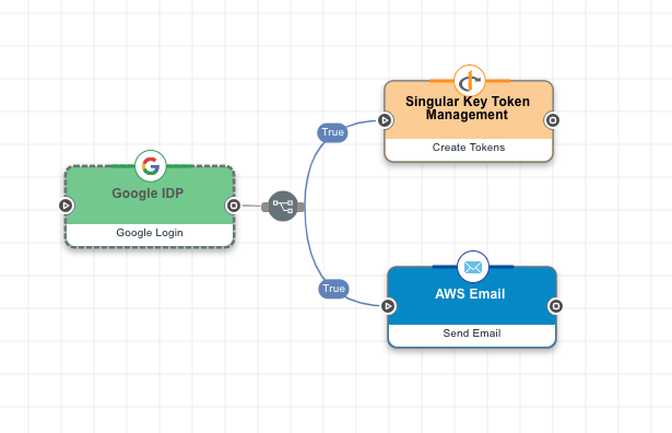
One node can trigger more than one additional node when it completes. In this example, after Google login completes, the flow creates tokens for the user and sends an email to the user.
This example uses the same nodes as the previous example, but the email is only sent after the tokens have been successfully created.

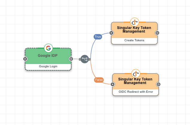
This example flow deals with a scenario where the Google IdP login fails. If it succeeds, the tokens are created, but if it fails, an error message is displayed.
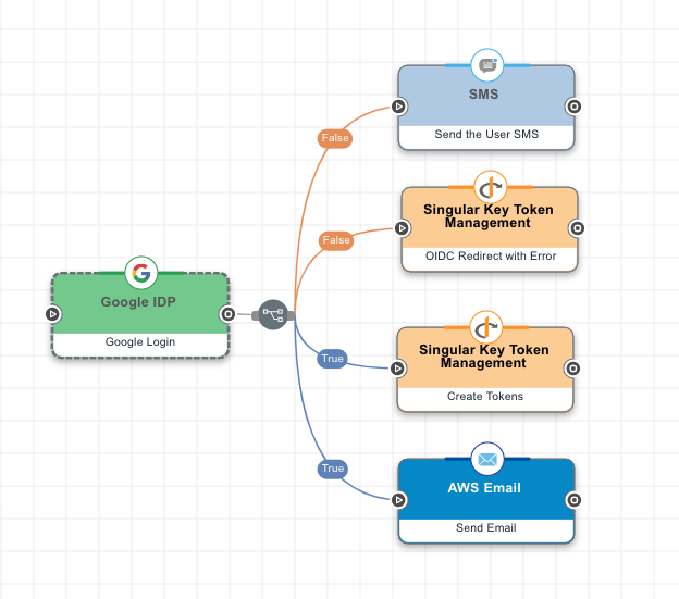
A single node can trigger multiple nodes, if it fails or succeeds. In this example, two nodes are launched if Google authentication succeeds, and two other nodes are launched if it fails.
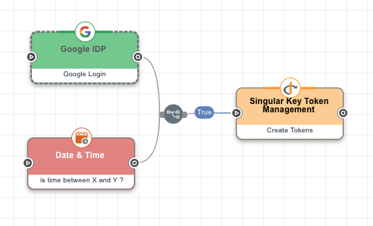
A node can have more than one trigger. In this case, the two trigger nodes have an AND relationship because the logical operator is "If All True". This means that the tokens are only created if the Google login succeeds and if the date and time are within the specified range.
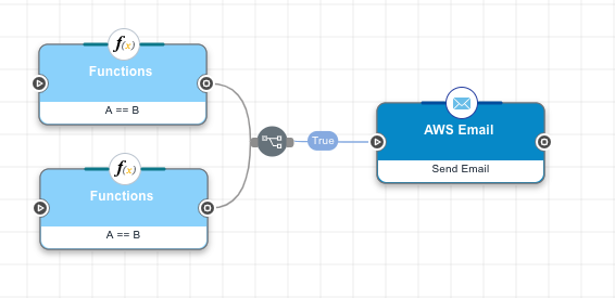
In this example, the two trigger nodes are linked to the Amazon Web Services (AWS) Email node by an "If Any True" logical operator, meaning that the email node is triggered if either of the initial nodes completes successfully.
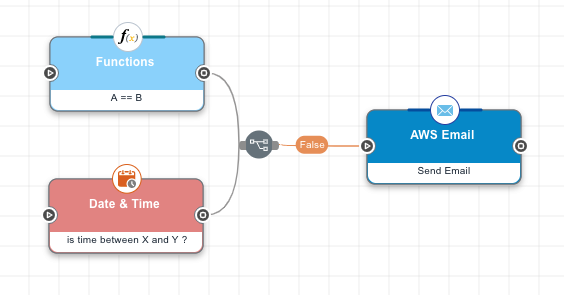
In this example, the AWS Email node is triggered if both of the preceding nodes complete unsuccessfully.
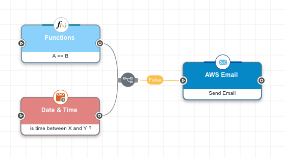
In this example, the AWS Email node is triggered if either of the preceding nodes completes unsuccessfully.
You can loop a node back to a previous node by clicking its output and drawing a line back to the earlier node. In this example, a Functions node checks the information provided on an HTML form and sends the user back to the form if the data doesn’t fall within the specified parameters.
|
You can’t loop back to the first node in the flow. |

Use cases
Flows are, by design, a broad toolset. This section explains the principles of assembling a flow. For examples of flows designed for specific scenarios, see the Use Cases section.